In today’s increasingly complex electromagnetic environments, the need for radiation hazards (RADHAZ) assessments and testing has reached critical importance. RADHAZ refers to the potential danger posed by radio frequency (RF) electromagnetic radiation. This term is commonly used in military, aerospace, and engineering contexts, especially in environments where high-powered RF transmitters are present. These dangers have traditionally been attributed to high-power intentional transmission equipment such as radars and long-range communications. However, low-power RF transmitters operating at close distances can also cause harm to personnel, ignite fuel, and initiate or disable electrically initiated explosive devices (EIDs).
This article will examine each of the three primary hazard areas covered by a RADHAZ assessment and dive into how these assessments are generally conducted. These hazard assessment areas cover:
- HERP (hazards of electromagnetic radiation to personnel)
- HERO (hazards of electromagnetic radiation to ordnance)
- HERF (hazards of electromagnetic radiation to fuel)
RADHAZ: Some Background
To illustrate the threat that RADHAZ presents, it is worth noting a historical incident that occurred during the late 1980s to early 1990s involving FLU‑12 life vest incidents aboard Aegis-class ships. There were three documented incidents where FLU-12 life vest EIDs were susceptible to the shipboard radar system (SPY-1), causing the life vests to inflate unintentionally. HERO occurs when RF energy couples to sensitive EIDs, including weapons, rockets, explosives, squibs, flares, igniters, explosive bolts, electric primed cartridges, destructive devices, and jet-assisted take‑off bottles. HERO may lead to triggering an unexpected explosion or disable the device, preventing it from performing as intended.
The life vest activations were reported during early operational deployments of these ships, suggesting the incidents likely occurred between 1987 and 1992, a period when HERO testing protocols were still evolving and the electromagnetic environment aboard Aegis ships was being actively characterized. While this event did not result in a catastrophic loss of life, it certainly depicts the threat electromagnetic radiation presents on ordnance devices, as well as the importance of well-executed modernized electromagnetic control plans.
Today, the HERO risk has evolved due to the gradual implementation of extremely powerful communications and radar equipment that radiate high levels of EM energy. This, coupled with the rapid deployment of advanced technologies consisting of EM sensitive, low-power electronics, is increasing HERO concerns to new levels. As a result of these growing risks, each service branch has placed an emphasis on verifying that all electrically initiated ordnance devices provide sufficient protection against their intended electromagnetic environment (EME), and that their performance is quantified through testing and/or analysis.
HERO Classifications
There are four classifications pertinent to HERO, as follows:
- HERO SAFE ORDNANCE
- HERO SUSCEPTIBLE ORDNANCE
- HERO UNSAFE ORDNANCE
- HERO UNRELIABLE ORDNANCE
HERO classifications are based upon the degree of susceptibility experienced while the ordnance is in each of its stage-to-stockpile (S⁴) configurations. In accordance with governing DoD standards such as MIL‑STD-464, ordnance that meet this qualification criteria require no RF environment restrictions beyond the general HERO requirements, and are classified as HERO SAFE ORDNANCE. Alternatively, ordnance determined to be susceptible and that require moderate RF environment restrictions are classified as HERO SUSCEPTIBLE or HERO UNSAFE/UNRELIABLE. These may include items that have never been evaluated for HERO, or items that have been classified as HERO SAFE but that can have increased exposure to an RF environment when assembled or disassembled.
While basic HERO requirements for design and performance verification are found in MIL‑STD-464 and other military standards, military service branches (Army, Navy, and Air Force) have developed unique approaches to deal with HERO problems over time. These approaches typically reflect other factors, such as how services store, transport, and use ordnance to minimize hazards.
When operational electromagnetic environment (EME) levels exceed susceptibility thresholds, the services can opt to use different risk-reduction measures. For example, the Army or Air Force might stipulate a minimum separation distance between the susceptible ordnance and the offending transmitter, while limited space aboard naval platforms/systems might leave no other option for the Navy than to impose restrictions on the emissions of the offending transmitter.
Nonetheless, the service groups deploy many different methodologies to manage HERO while minimizing the operational restrictions, such as frequency management, reducing the transmitter output power, or limiting the antenna radiation zones.
HERO Assessment Fundamentals
Despite these differences, there are common fundamentals applied to all HERO programs. Arguably, the most critical aspect is defining the sources contained within the EME for each platform, specifically, understanding the EME where ordnance will be used. In many cases, the EME is very complex, consisting of a large number of sources over a broad frequency spectrum. RF surveys are routinely performed at all ordnance S⁴ areas to keep this data up to date and allow it to be compiled into simple limit curves for use in HERO assessments.
The HERO SUSCEPTIBLE and HERO UNSAFE limit curves shown in Figure 1 were derived from a tri-service effort, where the HERO test data for each of the services was used to develop composite “worst-case” curves that are now harmonized across all U.S. DoD service branches.
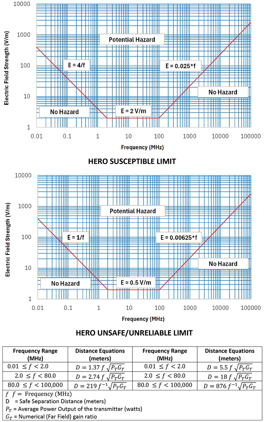
These curves represent the maximum allowable electromagnetic environment (MAE) for ordnance and are used to calculate the safe separation distance (SSD) between known transmitters and ordnance once the ordnance item is classified as either HERO SUSCEPTIBLE or HERO UNSAFE/UNRELIABLE. Specific details regarding the transmitter device must be known, including a list of transmit frequencies or transmit frequency bands used, as well as the average transmit power levels at each frequency. Selecting the lowest frequency for a given frequency band is permissible. But the gain of the transmitter at each selected transmit frequency is required. The effective isotropic radiated power (EIRP) is needed, but it can be calculated using the following formula:
Where:
Pt = output power (dBm)
Lc= cable loss (dB)
Ga= antenna gain (dBi)
This data is generally gathered from the manufacturer’s commercial EMI/EMC compliance test reports or through physical measurements. Additional information, such as transmitter type, modulation scheme, characteristics, antenna pattern plots, typical orientation, use, and modes of operation, is not required but can be useful supporting data when compiling the report.
Typically, HERO power density levels are exceeded by high-power intentional transmitters with high-gain antennas. The maximum power density at a given distance or maximum distance to a given power density can be calculated using these far-field equations. In the far-field region, the power density is calculated within the 3 dB beam width of the transmit antenna using the following formula:
Where:
Pd = power density ![]()
PT = average or peak transmitter
output power (watts)
G = numerical antenna gain (unitless)
r = distance from the antenna (meters)
Since most antennas used in these applications are aperture-type and the power density levels are only exceeded at near-field distances (where power distribution is a function of illumination taper), far-field calculations are often found to be excessive. Further guidance can be found in NAVSEA OP 3565 Volume 1 on how to calculate the near-field gain reduction factor.
Calculating HERO Safe Separation Distances
Traditionally, the founding philosophy of HERO was to ensure that a minimum ten-foot separation distance between all ordnance (including HERO SAFE ORDNANCE) and transmitters was maintained at all times. This included large stational high-power systems as well as most portable, mobile, and handheld systems. Exceptions to this ten-foot rule have been made primarily due to the increased use of low-power RF transmitting devices needed at distances closer than ten feet from ordnance.
Examples of these RF devices include wireless laptops, handheld devices, tracking devices, and passive or active radio-frequency identification devices (RFID) using automatic identification technology (AIT) and operating at very low power (i.e., less than 1 watt). In these examples, relaxation of the standard ten-foot SSD distance down to a distance of zero feet between the antenna and ordnance item (excluding physical contact) can be determined using the HERO safe separation distance calculations shown in Figure 1.
HERF Assessment Considerations
HERF concerns the accidental ignition of fuel vapors by RF-induced arcs during fuel-handling operations. Fuel‑handling is defined as the transferring of fuel from one container to another. While the probability ofHERF occurring is not common, accidental combustion is still possible.
There is not much information available with respect to HERF. However, guidance documents such as TO 31Z‑10‑4, and NAVSEA OP 3565 Volume 1 specify that areas where RF power densities exceed 5 W/cm2 (50,000 W/cm2) are considered to be hazardous areas for refueling operations regardless of the source of RF energy.
The SSD can also be calculated for HERF to establish the distance from a transmitting antenna where the power density will be approximately 5W/cm2. Much like with HERO SSDs, the actual separation distance between the transmitter and fuel should be established at a greater distance than calculated to ensure that the power density in the fueling area will be less than 5W/cm2.
The HERF SSD can be calculated using the following formula:
Where:
PD = desired power density (in W/m2) = 5 W/cm2 = 50,000 W/m2
D = distance (meters)
P = peak power (Watts)
G = antenna gain ratio ![]()
An additional equation may be used to calculate the separation distance required to achieve a power density equivalent to that existing 50 feet from an antenna radiating 250 watts (equivalent to 0.009 mW/cm2 or 0.09 W/m2).
Where:
PD = desired power density (in W/m2) = 5 W/cm2 = 50,000 W/m2
D = distance (meters)
P = peak power (Watts)
G = antenna gain ratio ![]()
HERP Assessment Considerations
The biological effects of non-ionizing (electromagnetic) radiation on personnel (HERP) can cause overheating of human body tissue. Overheating occurs when the body is unable to cope with or adequately dissipate heat generated by exposure to RF energy. However, the body’s response is dependent on the energy level, time of exposure, and ambient temperature.
Unlike ionizing radiation, no cumulative effects from repeated exposure or molecular changes that can lead to significant genetic damage to biological tissues have been proven. RF exposure guidelines and procedures have been adopted and promulgated to protect DoD personnel from the deleterious effects of RF exposure. DoDI 6055.11 implements the HERP criteria for military operations.
The transmitter must comply with the current DoD criteria for the protection of personnel against the effects of electromagnetic radiation. This DoD policy is currently found in DoDI 6055.11, and compliance is verified by test, analysis, or a combination of both.
Radar and ECM systems usually present the greatest potential personnel hazard due to their high transmit power levels and high-gain antenna characteristics, coupled with the potential of nearby personnel exposure. This poses the greatest risk to repair and facility maintenance personnel due to their frequent proximity to radiating elements and the need for rapid maintenance response.
In accordance with applicable standards, an RF hazard evaluation may be performed first by determining the SSD for personnel via calculations based on RF emitter characteristics or through measurement. Once the distance has been determined, an inspection is typically conducted in personnel access areas where exposure to the antenna’s main transmission beam is possible. Verification of appropriate warning signs, safety zones, and other precautionary measures, guidance manuals, and operating manuals is commonly required as part of the platform inspection process. Further technical guidance for assessing RF hazards can also be found in the Air Force AFRL-SA-WP-SR-2013-0003, Army TO 31Z-10-4, TB MED 523, and Navy NAVSEA OP 3565.
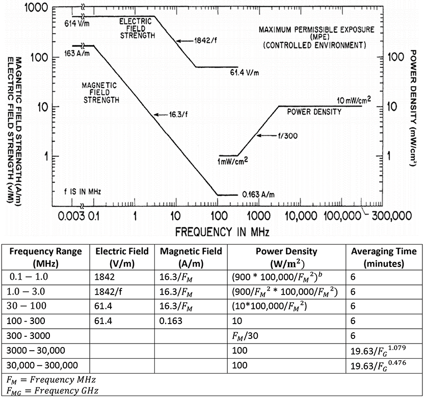
The HERP limits are established as MPE values based upon the basic restriction. The upper tier MPE limits shown in Figure 4 are presented as a function of frequency, and their values have been based upon a whole-body specific absorption rate (SAR) of 0.4 W/kg (formerly known as “controlled”).The limits were developed to control human exposures to electromagnetic energy at frequencies ranging from 0 kHz – 300 GHz, and to limit the localized SAR occurring in the feet, ankles, wrists, and hands of personnel due to exposure to such fields or contact with objects exposed to such fields. MPEs are given in terms of rms electric (E) and magnetic (H) field strengths, equivalent plane-wave free space power densities (S), flux density (B), and induced currents (I) in the body.
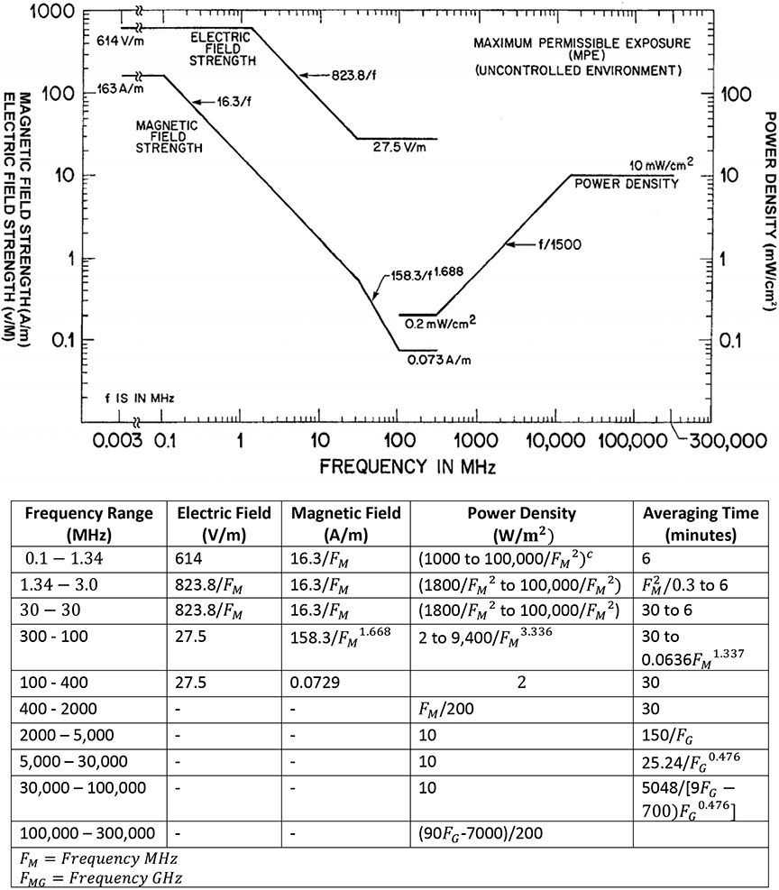
The lower tier MPE limits shown in Figure 5 are presented as a function of frequency and are based on a SAR of 0.08 W/kg lower tier (formerly known as “uncontrolled”) exposures that can occur in areas where individuals would have no knowledge or control of their exposure. These locations would include living quarters or workplaces where there are no expectations that the exposure levels may be exceeded.
Other Considerations
HERP SSD may be validated through physical EMI survey measurements using specialized HERP/RADHAZ meters to ensure the proper tier limits are not exceeded. However, caution is needed to ensure that the field measurement probes used have peak power limits above the expected peak and average levels at the SSD distance. This will prevent potential saturation and/or damage of the measurement device. This should include scenarios where multiple emitters are present and the emitters are not phase coherent (the usual case), causing spectrum power density. This is an important effect which should be considered for both calculation and measurement approaches.
In addition to the main beam hazards, localized hot spots produced by reflections and resonant standing waves occurring between metal structures and buildings is also an important consideration. It is common to encounter these scenarios in areas where general power densities are initially found to be less than the maximum permissible exposure limits. Therefore, a thorough understanding of the site and the surrounding electromagnetic environment is critical.
There are several guidance documents available to assist in EMI survey planning as well as typical test methodology and measurement equipment recommendations based on the platform and type of transmitter.
Conclusion
In summary, RADHAZ is a very important safety aspect of today’s U.S military force, and assessment is typically required for any new RF transmission device prior to deployment, including those that are specifically intended for operation in proximity of ordnance, fuel, and personnel.