
Building IEC 61000-4-2 Compliant Test Equipment on a Budget
Our internal EMC laboratory had decided to verify (not certify, as it’s not an accredited lab) all the equipment we use for pre-compliance EMC tests. The goal was to find some defective equipment and to repair or replace it to avoid the possibility of generating inaccurate test results.
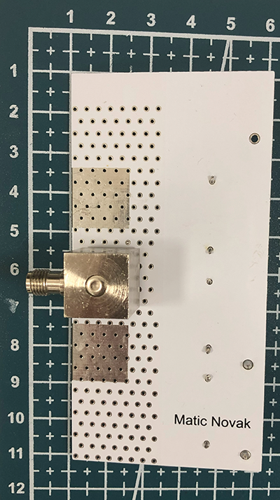
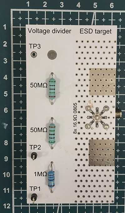
One of the trickiest pieces of equipment to verify was the ESD gun because specialized equipment is needed for the verification test. Off-the-shelf ESD targets are relatively expensive (>1500 USD), so we decided to build a do-it-yourself (DIY) version. (See our final design in Figure 1 and Figure 2.)
DIY ESD Target Overview and Design Choices
After reading through IEC 61000-4-2, Testing and measurement techniques – Electrostatic discharge immunity test, which specifies the type of ESD target to use and its calibration procedure, and reading some articles on the topic, we decided to make the circuit in two separate parts, including a voltage divider and an ESD target.
The requirement for the maximum tested ESD voltage was set at 15 kV. The voltage divider was made by simply placing 100 MΩ and 1 MΩ high voltage resistors in series (HVR3700001004FR500 and HVA12FA50M0). We used two 50 MΩ in series to increase the voltage rating of the resistors we used. A single 50 MΩ resistor withstands a maximum voltage of 8 kV. So, with two in series, our device could withstand a maximum voltage of 16 kV. Three test points were placed so that connections with the ESD gun and multimeter would be easier to make.
We constructed our ESD target by finding a connector with enough distance between the center pin and the outer pins to fit eight 16.5 Ω 0805 SMD resistors connected in parallel (ERJ‑P06F16R5), which defines the <2.1 Ω input impedance at DC, consistent with the IEC 61000-4-2 standard. 2.0625 Ω is the equivalent input impedance of the eight 16.5 Ω selected resistors placed in parallel, which satisfied the criteria in the standard of under 2.1 Ω.
Resistors were chosen as they have the maximum voltage of 400 V. Maximum voltage during the ESD event would be 15 kV (max voltage requirement)/(330 Ω (output impedance of the ESD gun)/2.1 Ω (impedance of the ESD target)) = 96 V. The maximum voltage can reach a slightly higher value (due to a parasitic capacitance in the ESD gun) that is in parallel to the 330 Ω resistor, which allows for higher current. The ESD target resistor’s datasheet also specifies resistance to 3 kV ESD pulses.
Our chosen connector has an SMA connector and a distance of 7 mm between the center and outer pins. A similar part with an N-type connector can be chosen for a similar pin distance. Some copper was exposed with plating to more easily connect the grounding clip of the ESD gun.
Comparing DIY ESD Target to the IEC 61000‑4‑2 Standard (Input Impedance, Insertion Loss)
We measured the input impedance using a 1 A current source and a multimeter, resulting in a value of 2.08 Ω. The circuit diagram for this measurement is shown in Figure 3, but this measurement was done only with the target in the measurement chain. Insertion loss is defined in IEC 61000-4-2 as ±0.5 dB up to 1 GHz, and ±1.2 dB from 1 to 4 GHz, with respect to the nominal value S21 of the insertion loss, as described in Equation 1.
Rin is the DC input impedance of the target-attenuator-cable chain, when loaded with 50 Ω, which was measured as 2.03 Ω. A circuit diagram of the measurement is shown in Figure 3, where the input voltage was divided by Isys, resulting in 2.03 Ω.
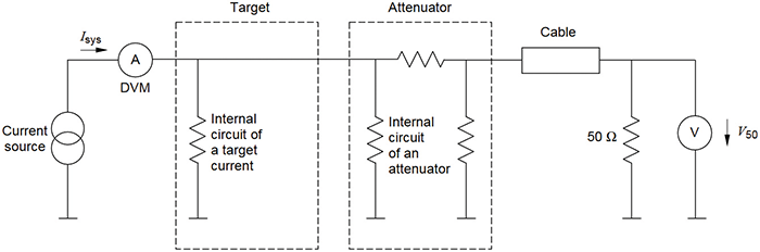
Meanwhile, the low-frequency transfer impedance of the same chain, labelled Zsys, was measured at 0.197 Ω. This is also shown in Figure 3, where V50 is divided by Isys to obtain this value. S21 was then calculated as -42.4 dB with Equation 1.
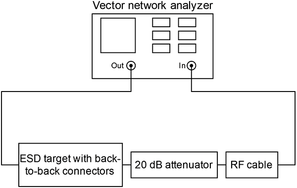
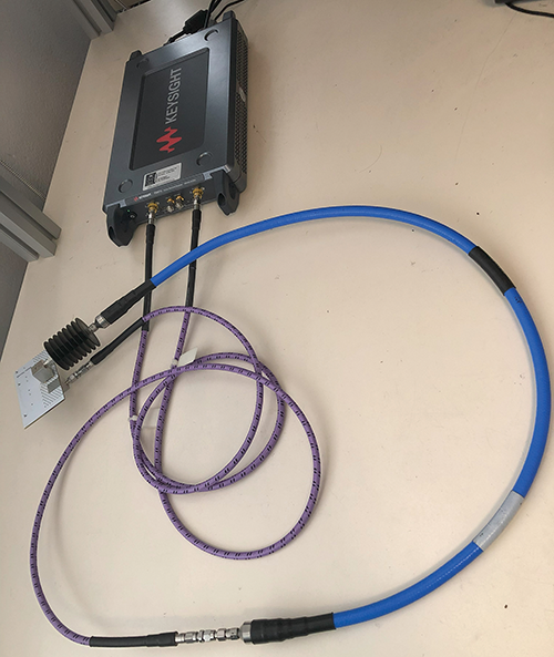
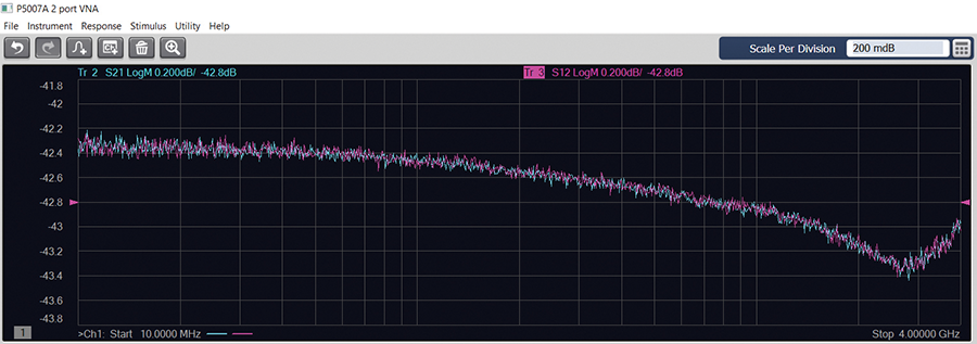
Insertion loss measurement was performed using a Keysight P5007A VNA. The EUT was the ESD target with a soldered connector, resulting in a back-to-back test sample. RF cable and 20 dB attenuator were in the test chain. (See Figure 4 for the measurement diagram and Figure 5 for test setup photo.) The measurement shown in Figure 6 was just within the 0.5 dB requirement up to 1 GHz.
IEC 61000-4-2 also references a vertical calibration plane with the ESD target mounted in the center. This is to prevent radiated pulses from interfering with the oscilloscope, together with a Faraday cage. This was necessary in the past when the analog oscilloscopes were not significantly shielded. But today’s digital oscilloscopes should be less sensitive to the radiated pulses of an ESD gun. Our test did not use the vertical calibration plane, but it can be seen as a potential upgrade.
When we tried testing 15 kV contact discharges, the oscilloscope had an error, which was resolved with a reset.
Hence, when using high-voltage discharges and tips with a short rise time, a vertical calibration plane would be beneficial.
Verifying the ESD Gun’s Voltage
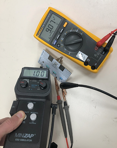
The ESD gun was grounded at test point 1 and the discharge tip was placed at test point 3. (See Figure 7 for the test setup diagram and Figure 8 for the test setup photo.) The voltage of the ESD gun in this example was set to 1000 V. ESD discharge did not occur, as the resistance was too high to discharge the internal capacitor. A multimeter was set to DC voltage and placed on test point 1 and test point 2 to measure voltage on the 1 MΩ resistor.
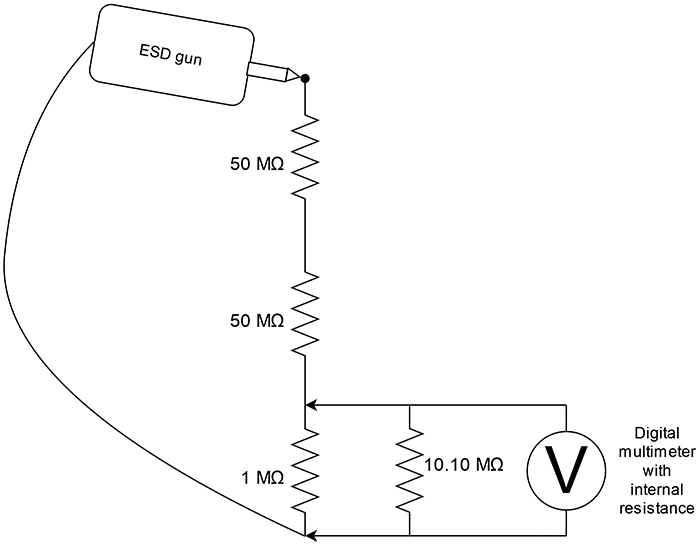
It was important to take into account the internal resistance of the multimeter on the specific voltage range we were measuring. This should be measured with a second multimeter set to resistance mode and the first multimeter should be manually set to the voltage range that will be used during voltage measurement.
The measurement showed an internal resistance of 10.10 MΩ on the 60 V range. We added 9.8% to the 9.07 V measurement to correct for the multimeter’s internal resistance and then multiplied the result by 101 to get the ESD gun voltage from the resistor divider. And we got the final measurement of 1005.8 V, which was within the 5% of output voltage tolerance, as described in IEC 61000-4-2.
Verifying ESD Gun’s Pulse Shape
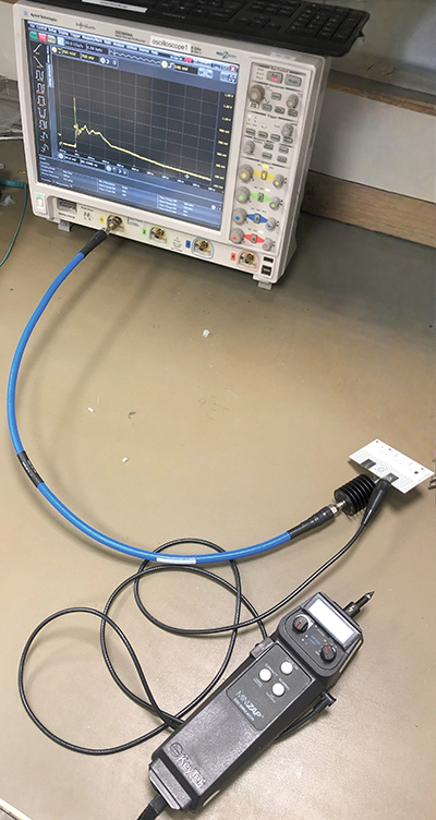
We used a DSO9404A oscilloscope from Agilent with a BW of 4 GHz and 20 GSa/s. The used channel was in the 50 Ω mode (we were careful not to overload the input!). The ESD target was connected to a 20 dB attenuator with a frequency range of DC-18 GHz. We checked the attenuator datasheet to ensure it could withstand the ESD pulse. (Note that it sees only the voltage on the 2.1 Ω impedance (~116 V at 15 kV pulse)). The RF cable had low attenuation at 4 GHz, passing the ±1.2 dB requirement in IEC 61000-4-2.
We connected the ground clip of the ESD gun to the exposed GND pad on the ESD target and placed the contact discharge tip to the center pin of the ESD target. The oscilloscope was set to a single trigger. (See Figure 9 for the test setup and Figure 10 for the resulting waveform.) Tektronix application notes mention that ripples in the captured waveform are due to a small calibration plane, which we didn’t verify.
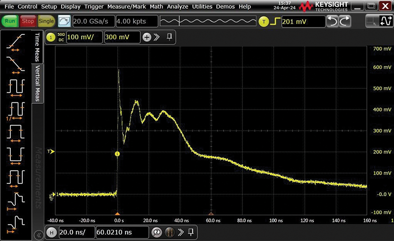
Peak voltage was measured at 590 mV, which should be divided by the Zsys – 0.197 V/A, to get 3 A of measured current. The voltage at 30 ns was 390 mV (1.97 A); at 60 ns, it was 175 mV (0.89 A). Rise time was measured at 0.6 ns. We found that the rise time of some tips is much shorter than others. It can be as low as 100 ps, which makes the ESD test harder to pass because the pulse then contains higher signal frequencies that are harder to filter out. In the accredited labs, they should have a tip with a rise time of about 0.8 ns.
Pulse shape for 1000 V ESD discharge is defined in IEC 61000‑4‑2 with these parameters:
- First peak current of discharge is 3.75 A ± 15%
- Rise time is 0.8 ns ± 25 %
- Current at 30 ns is 2 A ± 30 %
- Current at 60 ns is 1 A ± 30 %
All of our measurements passed the standard’s requirements, except the first peak current of discharge, which was 3 A and should be a minimum of 3.19 A. This is most likely due to the specific tip that was used for this test (Keytek model MZ TPC-2A). Other tested tips had a much higher first peak current and faster rise time. We also tried to test air discharge by placing Kapton tape around the discharge pin on the ESD target to cover the GND pins. Kapton tape has a 4 kV voltage resistance, so a few layers are enough to withstand the 15 kV pulse.
We should note that the pulse shape tests are not completely reproducible, because small differences in the positioning of the ESD gun and ESD target can change the results slightly. When testing air discharge, the approach speed will change the measured pulse. We also tested 15 kV contact discharges with an additional 20 dB attenuator to limit the voltage to the oscilloscope channel under 5 V. The ESD target worked as expected but, with the high rise time ESD gun tip, the oscilloscope had an error, which was resolved with a reset.
Conclusion
The DIY ESD target is useful for pre-compliance laboratories that do not require accredited equipment for their measurements but that verify testing equipment every year to make sure it still works as expected. Compared to an off-the-shelf ESD target, the DIY version is much less expensive but it still provides good measurement accuracy based on the IEC 61000-4-2 standard. A potential improvement would be to make the ESD target mountable in a vertical calibration plane, which would improve the oscilloscope’s immunity to radiated ESD pulses.
References
- International Electrotechnical Commission, “IEC 61000-4-2, Electromagnetic compatibility (EMC) – Part 4-2: Testing and measurement techniques – Electrostatic discharge immunity test.”
- Tektronix, “Troubleshooting ESD Failures Using an Oscilloscope.”
- Kenneth Wyatt, “Check ESD Simulators First,” EDN, August 1, 2008.