
Beyond Static Testing: Integrated Approaches for EV EMC Validation
The shift from internal combustion engine (ICE) automobiles to electric vehicles (EVs) has come with an array of new subsystems and components that introduce new EMC considerations. The level of complexity involved in automotive electromagnetic compatibility (EMC) testing increases with dynamic driving conditions, where manufacturers not only have to refer to the framework standards offered but must also improvise and establish new internal standards to ensure the vehicle and its internal components all function properly under all driving conditions. A number of challenges may arise when building a suitable test bench that thoroughly tests EVs and electrical components.
This article discusses the importance of EMC testing in the automotive industry, as well as dynamic EMC test systems and their inherent challenges. It also describes the development of a unified EMC test platform for dynamic driving conditions.
The EMI Influence of the E-Drive
As electromobility rapidly evolves, a growing number of OEMs are adding battery EVs (BEVs) with an electrified powertrain to their product offerings. The electric powertrain consists of two main components:
- High-voltage battery system
- E-drive (inverter + electric motor)
Both systems directly contribute to electromagnetic interference (EMI). E-drives are generally composed of one to two electric motors and a high switching frequency inverter to control the electric motors (see Figure 1). They are often permanent magnet machines (PMM), where high-performance PMMs offer up to 500 Nm of torque and 35,000 rpm. Such performance is challenging to test on test benches limited to an enclosed space.
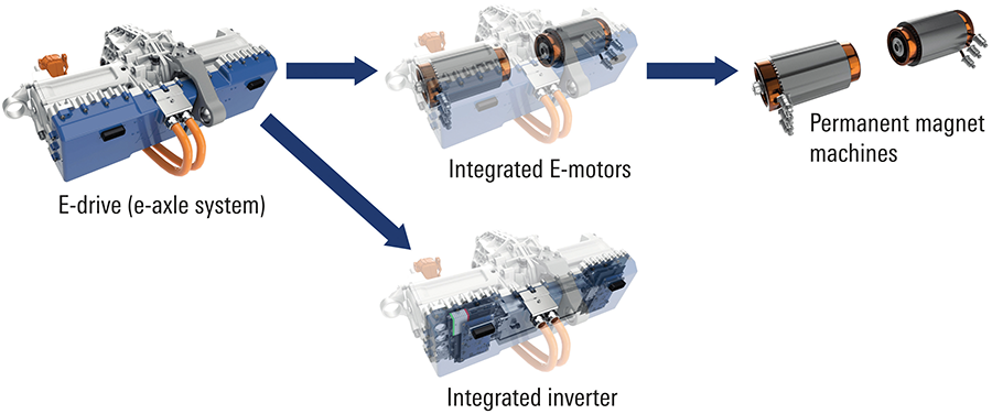
The most critical component in terms of EMC is the inverter. These operate on high battery voltages and use rapid switching frequencies to enhance controls, power output, and efficiency. The fast switching of high currents from a few kHz to well above 10 kHz and the fast switching of high voltages with steep gradients causes unwanted EMI. This problem will worsen as more and more GaN inverters are introduced, as their RF output is anticipated to reach up to ten times the value of traditional IGBTs.
The EMI problem worsens with the integration of more sensors and communications technology (e.g., Bluetooth®, Wi-Fi, LTE) that may be easily disturbed by the EMI from the E-drive. Sensitive radar, LiDAR sensors, and cameras that are integrated into ADAS systems will be affected by excessive EMI. This is an unacceptable risk in safety-critical systems such as brake assistance and cruise control, making EMC testing a top priority for OEMs.
A Look at Automotive EMC Testing
EMC Testing: Overview
As shown in Figure 2, EMC testing can be broken down into EMI and electromagnetic susceptibility (EMS). EMI can be defined as the unintentional emissions from the equipment under test (EUT), while EMS measures how much disturbance is possible before the EUT stops working.
It is vital to begin EMC testing at an early stage of development, as modifying components in an already developed vehicle will be costly and time-consuming. Figure 3 shows EMC test benches for component testing and vehicle testing. Test benches have grown in complexity. For example, e-axle tests might involve an environmental chamber or a thermal condition system to simulate environmental conditions, as well as two oppositely mounted load machines (motors) that connect to the output shafts of the e-axle. This simulates the vehicle at various speeds and road gradients in different driving conditions.

The Challenge of Testing at Typical Operating Conditions
The critical challenge for EMC measurements lies in the car mimicking real driving conditions as closely as possible. It is not enough to have a vehicle idling or completely motionless, as it would be difficult to characterize the system’s electromagnetic noise properly. Standards create rough guidelines for testing EVs, so even when adhering to these requirements, the product still may not perform as anticipated.
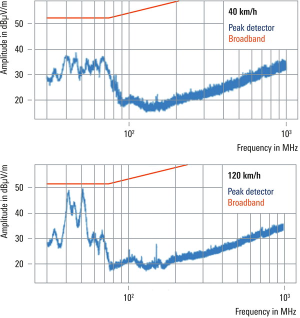
As an example, the CISPR12 standard requires EVs to be tested while at a constant speed of 40 km/h. However, emissions are quite different at varying speeds (Figure 4). When the vehicle runs at a speed of 120 km/h, emissions nearly reach the CISPR12 standard limits. This problem becomes even more pronounced under dynamic vehicle conditions such as vehicle acceleration or speed reduction and battery charging (recuperation).
The Challenge of Testing Under Dynamic Speed and Recuperation
Figure 5 shows the load change effect on the high voltage (HV) line. There are higher broadband interference emissions when the car is accelerated or decelerated that go well above the limit of the CISPR25 Class 5 standard.
Figure 5: EMC measurements on HV line with current probe at 100 Nm and 200 Nm torque levels with CISPR peak (Pk+) and CISPR average (AVG) detectors
(Note: The measurements were performed in a precompliance environment. The background level interference emissions are higher than demanded by the standards.)
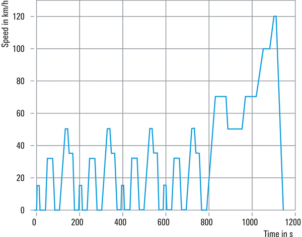
Setting these dynamic speed (rpm) and torque (Nm) conditions on an EUT has grown in complexity. In the past, it was possible to run EMC test software on a vehicle that was simply running at a constant speed. However, this is not sufficient for accurately characterizing a vehicle’s emissions. Now, more complex speed profiles or driving cycles (DC) are used for vehicle energy simulation and evaluation with standard profiles such as the worldwide harmonized light vehicle test cycle (WLTC) and new European driving cycle (NEDC) for Europe and 10 mode (J10) for Japan (Figure 6).
However, there are still more operating conditions that must be tested in a specific sequence, including:
- Constant speed
- High speed
- Low speed
- Acceleration
- Deceleration
- High torque
- Low torque
In other words, several parameters (e.g., speed, torque, current, voltage) will change at different times to more effectively simulate real driving conditions in various environments (e.g., rural, city, highway, mountain, cold, hot). The main test challenge lies in synchronizing the measurement flow (all the parameter values) between the EMC measurement software and the test bench. Since there is now more functionality integrated into the test bench itself, the synchronization becomes more difficult.
Finding worst-case issues with the EUT by varying parameters such as torque and speed, for example, requires more advanced communications between the EMC automation software and the test bench that simulates the road and driving conditions.
The Landscape of EMC Standards
There are many EMC standards available for vehicle testing, including ISO 11451 series for full vehicle EMS and ISO 11452 series for subassembly EMS testing. The CISPR series is often referred to for emissions with off/onboard receivers and wireless power transfers. Additionally, there are regional standards such as the GB, Chinese standards. Certain EMC standards reference all of the more general standards but add details or apply modifications. The UN ECE R10 standard for EMC homologation/approval of vehicles, for example, is more or less globally applicable and a minimum OEM requirement.
On top of this, OEMs add their own EMC testing standards and requirements. While some may change a few parameters to modify the testing to their own specific needs, most will raise the bar of the general standards even higher. Existing EMC standards may not be sufficient to ensure their products work properly. Establishing international standards is often a long, drawn-out process that involves studies, multiple proposals, and alignment between different parties.
A New Approach to Dynamic Automotive Testing
A Look at an Automotive Test Solution
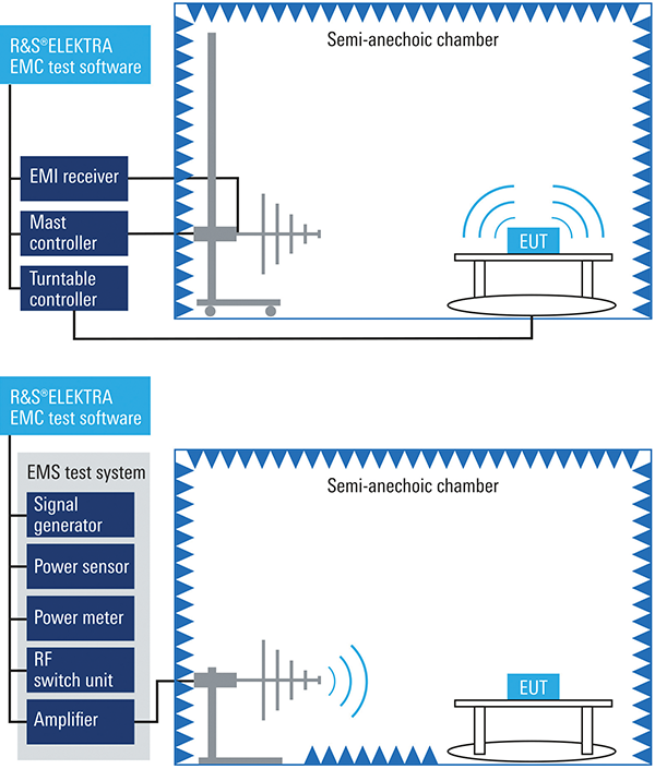
Figure 7 shows the automotive test solution for EMC testing under dynamic conditions that our technical experts have developed in partnership with AVL, a mobility technology company. At the center of this approach is the device under test (DUT) or EUT that can be an e-axle, an electric motor, or even an entire vehicle. On the left is the complete EMC test system that includes automation software, an EMI receiver, a generator, an amplifier, antennas, and a turntable. On the right is the complete test bench that will vary depending on the EUT. It includes test bench control software, a battery simulator, a chassis dynamometer, motor control, an environmental chamber, etc.

Test System Synchronization
In the past, users would need to use the software for the EMC test system and test bench separately, but in parallel, to perform any testing. This task becomes much more complicated under dynamic conditions with varying sequences of torque, speed, etc. The integrated approach ensures that users operate only one software package while the other is automatically remote-controlled. Figure 8 shows a block diagram with some of the test synchronization.
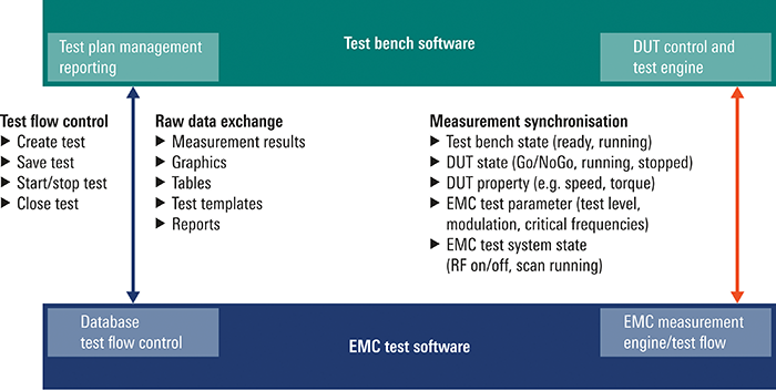
For measurement synchronization between the EMC measurement test flow and the test bench/DUT control, the test bench state, DUT state, DUT properties, EMC test parameters and EMC test system state are communicated constantly and analyzed for progress in real time. For example, EMC test parameters such as the test level, modulation, and critical frequencies represent necessary information to transmit to the test bench software. Measurement results, graphics, tables, and reports can also be transferred from one software package to the other. But, for this to happen, many interfaces are necessary, as well as a database in both software packages.
Implementing Dynamic EMC Testing
Practical implementation of synchronized dynamic EMC testing involves several key capabilities. The system must be able to automatically cycle through various operating conditions (speed, torque, load) while continuously monitoring EMC parameters across the frequency spectrum. During testing, the system identifies critical frequencies where emissions peak under specific operating conditions, then automatically returns to those exact operating points for detailed analysis. This approach reveals problematic frequencies that might be missed in static testing and provides the precise operating conditions where compliance issues occur. For EMC testing, the system can evaluate device performance with and without applied loads at each test frequency, providing a complete picture of how dynamic conditions affect EMC performance.
Summary
From high-voltage battery packs and high‑performance E-drives to advanced in-vehicle functions and communications technologies, vehicles are growing in complexity. This added complexity is creating new EMC challenges where current EMC standards do not yet cover the issues affecting newer systems/vehicles, such as EVs and ADAS functions. EMC has the greater challenge of testing under dynamic, or more realistic, driving conditions to characterize an EUT’s EMI and EMS accurately.
This is a challenge that often involves users manually controlling the test bench software and EMC measurement system, with little to no collaboration between the two systems. The combined approach presented in this article provides full testing coverage in one integrated system, where one software package can remotely and automatically control the other. This eases EMC testing – particularly dynamic automotive testing – where complex sequences can be easily run.
The combined solution also simplifies testing for OEMs with custom-tailored EMC testing and allows companies to be ahead of the market and easily prepare for new EMC compliance requirements with testing beyond current established standards.